Page 1 of 1
Cutting Accuracy
Posted: Mon 25 Jan , 2021 16:36 pm
by Yojevol
Having got to grips with software and G-code inputs to my recently acquired Compact, I now have a question concerning accuracy of following toolpaths.
On my first few designs I became aware that they were all exhibiting dimensional errors. So I set up some test pieces culminating in this one:-

to try and make sense of what was going on.
I've taken 40 odd dimensions off this and my conclusion is that the 4mm end mill is cutting over the design line by about 0.24mm on the X-axis and about 0.12mm in the Y.
My first thought was that I had inadvertently put in a -ve roughing allowance, but checking the G-code this was definitely not the case and anyway there would not be a difference between X and Y.
I would appreciate any views on the cause and possible remedies.
Brian
PS the image doesn't seem to be working. It's a Dropbox link. However I think my words are sufficient
Re: Cutting Accuracy
Posted: Tue 26 Jan , 2021 18:37 pm
by Steve
What material are you cutting?
Have you measured the width of a slot made with your cutter? Is the cutter running true?
Re: Cutting Accuracy
Posted: Wed 27 Jan , 2021 17:13 pm
by Yojevol
Thanks for your response Steve. Since putting up my post i have done some more tests to get a better feel for what's going on. My first tests were on rather poor quality MDF but my latest ones are on good quality plywood. The results are quite consistent.
I'm using a 5mm end mill and the cut widths are coming in at about 5.02. I have been cutting 25mm squares with both inside and outside cuts. Having measured lots of dimensions I calculated that there is an average overcut of +0.18mm. On my latest test I put in a rough cut allowance of 0.18mm and this has successfully minimised the errors. However there is a clear difference in errors in the X and Y axes such that they can never be eliminated by the rough cut allowance technique. The X-axis error is about +0.27mm and on the Y about +0.11.
I'm intending to use the m/c to make wooden clock parts and on the smaller pinion gears these errors may be significant.
Brian
Re: Cutting Accuracy
Posted: Wed 27 Jan , 2021 18:01 pm
by Yojevol
Further to my post above I have checked out the possibility of backlash.
On the X leadscrew there is a backlash of 0.33mm.
On the Y leadscrew there is no discernible play.
On the Z leadscrew there is no apparent vertical play. However there is significant play in the router carriage such deflection of 0.8mm in the Y direction is possible at the cutter tip with some force applied.
Brian
Re: Cutting Accuracy
Posted: Thu 28 Jan , 2021 0:16 am
by Yojevol
I've now had a look at the 3 XYZ assembly drawings. On the leadscrew nuts it looks as though there is some sort of wedge arrangement. Will it be possible to eliminate the X-axis backlash with this feature?
Also from the Z drawing it looks as though the play in the router mount may be due to loose lower attachment screws.
Any comments?
Brian
Re: Cutting Accuracy
Posted: Fri 29 Jan , 2021 13:04 pm
by Martin
Hi Brian
Have you checked that the play is not in the leadscrew?
The leadscrew is tensioned with a nyloc that clamps up against the bearing.
You can also look at cleaning out the nut on the leadscrew which you would have to remove. The nuts have a captive spring that should allow for any wear but the internal slots on the nuts can get clogged up.
https://www.reliance.co.uk/wp-content/u ... df#page=19
Re: Cutting Accuracy
Posted: Fri 29 Jan , 2021 18:43 pm
by TDIPower
Martin/Steve as always know there stuff (no surprise

)
Cleaning is important on these machines especially as a lot of the time in schools etc they are used with model foam, MDF and balsa, it get right in your nuts worse than a day at the beach!
I'm not 100% on the compact but when I was machining Oak on my microrouter I had to dial things back as I could see the whole gantry tip, leaning in to the cut as it went at it. Having never done Oak with it before it was a learning curve. I actually then went and found the Denford feeds/speed chart and used that as a base line and it was a good help.
Pete
Re: Cutting Accuracy
Posted: Sat 30 Jan , 2021 21:50 pm
by Yojevol
Martin wrote: ↑Fri 29 Jan , 2021 13:04 pm
Have you checked that the play is not in the leadscrew?
The leadscrew is tensioned with a nyloc that clamps up against the bearing.
You can also look at cleaning out the nut on the leadscrew which you would have to remove. The nuts have a captive spring that should allow for any wear but the internal slots on the nuts can get clogged up.
Thanks for your response Martin. You gave me confidence to strip the unit right down to the nut. I checked for play in the leadscrew en route but it was absolutely secure. It's difficult to imagine that nyloc nut coming loose. Here are a couple of pics of the nut:-
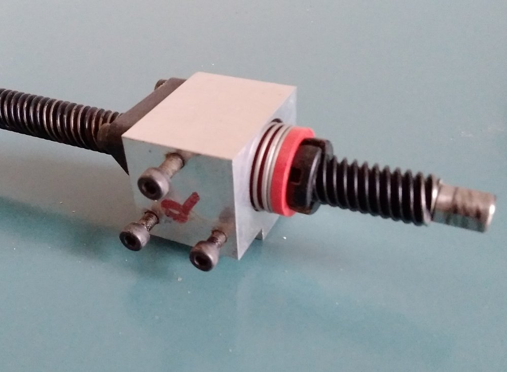
- 20210130_151310.jpg (68.59 KiB) Viewed 12473 times
- 20210130_151638.jpg (67.09 KiB) Viewed 12473 times
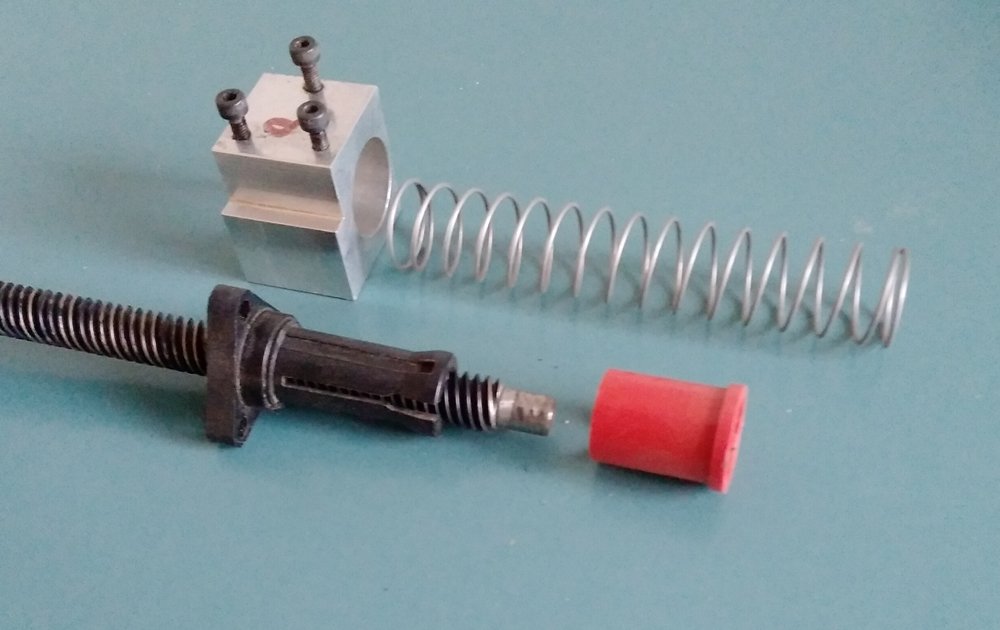
On dismantling the lead nut it became apparent that the black plastic threaded collet could not take any further adjustment to compensate for wear. The reason it had reached its limit was because the red outer sleeve had come to the end of its possible travel. However the collet is still capable of further tightening and this is how I intend to achieve it:-
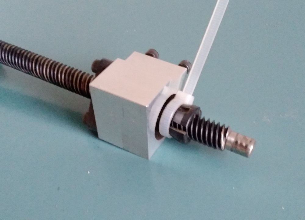
- 20210130_152335.jpg (66.32 KiB) Viewed 12473 times
Neat eh? And at no cost

There is still the minutest bit of backlash apparent and so I will swap it with the Z-axis nut which is in pristine condition. The worn one will have an easy retirement in the ZZZzzz.... zone where it will enjoy assistance from Mother Earth in the form of gravity.
Regarding my other source of play, all 8 sliders on the X and Z rails are worn. Here is one of them:-
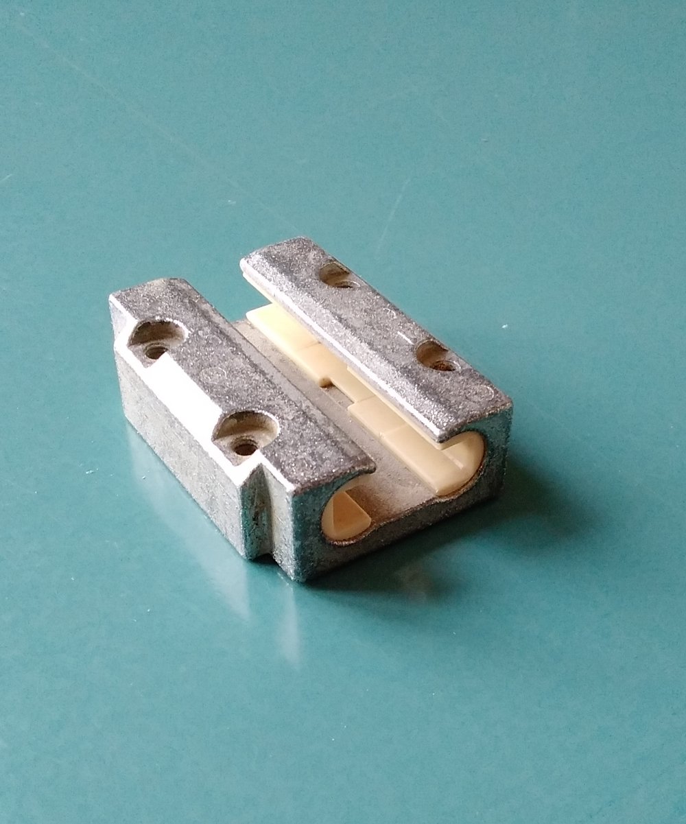
- 20210129_134857 (1).jpg (151.72 KiB) Viewed 12473 times
They no longer appear in the Reliance catalogue so I assume replacement plastic inserts are not available so that just presents me with a challenge. I will make my own. To that end I have a metre of 8mm nylon rod on order. I'll take a few pics as I do the job and present them here in due course.
TDIPower wrote: ↑Fri 29 Jan , 2021 18:43 pm
Cleaning is important on these machines especially as a lot of the time in schools etc they are used with model foam, MDF and balsa, it get right in your nuts worse than a day at the beach! I actually then went and found the Denford feeds/speed chart and used that as a base line and it was a good help.
Pete
Pete, I don't think the designers of this machine considered that cleaning was important, at least not in the leadscrew housings; the covers, especially the X, are a challenging task to remove, made worse by the use of unnecessarily small button headed screws. The screws may be strong enough for the job but the Allen keys and sockets are not. 3 of mine failed and I had to grind the heads off. I think I'll leave the covers off when I reassemble. Rant over.
Pete, is there a link to the feeds/speed chart you mention?
Brian
Re: Cutting Accuracy
Posted: Sun 31 Jan , 2021 19:12 pm
by TDIPower
Here it is.
Pete
Re: Cutting Accuracy
Posted: Tue 02 Feb , 2021 16:50 pm
by DavidB
Brian,
Have you looked for carriage equivalents elsewhere. I just saw this range at Igus and it looks similar
https://www.igus.co.uk/product/930 . The Igus material may be more suitable than nylon which can be annoying to machine.
Re: Cutting Accuracy
Posted: Wed 03 Feb , 2021 20:45 pm
by Yojevol
DavidB wrote: ↑Tue 02 Feb , 2021 16:50 pm
Brian,
Have you looked for carriage equivalents elsewhere. I just saw this range at Igus and it looks similar
https://www.igus.co.uk/product/930 . The Igus material may be more suitable than nylon which can be annoying to machine.
Thanks for that tip David. They are the actual manufacturers of my guides and can supply me with replacements at a reasonable cost. I need 16, there's 22 in the UK so I'm in.
Brian
Re: Cutting Accuracy
Posted: Thu 04 Feb , 2021 1:14 am
by DavidB
Brian,
That's a great result, hopefully you get a decent discount for buying most of the UK stock. I had originally thought of suggesting 3D printing the inserts in Igus filament as you can buy it from their site but I don't know if you have a 3D printer. It's something I've had in mind to try for a bit as I have a 3D printer but haven't had a project needing it yet.
Re: Cutting Accuracy
Posted: Thu 04 Mar , 2021 16:59 pm
by Yojevol
I thought I would close out this thread with a report now the refurbishment is finished.
Work done:-
1. Replacement of X and Z guide plastic inserts with self-made nylon ones. Replacement inserts from the manufacturer proved to be not so reasonable and would have amounted to nearly 10% of the value of the machine.
2. Tightening up of the Y guides by utilising the available adjustment in the attachment screw clearance holes. This virtually eliminated the possibility of racking of the table.
3. Swapping the X and Z lead nuts as outlined in my previous post above.
4. Replacement of the upper bearing in the Z stepper motor. This was unexpected. When recommissioning, the Z drive locked up solid. I stripped it all down to find the motor had a large quantity of wood dust inside and it had even penetrated the 'sealed' bearing. There was no other recourse other than to buy a replacement.
5. Flattening the Z drive guide mounting plate. Again something unexpected. When reassembling the Z guides I found it impossible to tighten the guide attachment screws without them binding on their guide rails. After a couple of hours dismantling and reassembling the whole system I discovered that the mounting plate was dished by about a ½mm. This was causing guides to move as I tightened the cap head retaining screws. I managed to flatten it sufficiently on my belt sander. It must have been like that from new.
6. There was a significant amount of dust accumulated under the drive dust covers, so I have reassembled without them to enable comprehensive vac'ing out after use.
Having done all this work I ran some repeat test cuts. I was very disappointed to find that errors were still apparent. The X direction error was reduced but both the X and Y errors seem to be more consistent. On average the cutter is over cutting the programmed line by about 0.1mm. I have experimented with correction factors and have produced satisfactory results by adding 0.2mm to the mill tool diameter. The same could be achieved by specifying a 0.1mm roughing allowance. This gives me a spot-on result in the X direction (as well as I can measure with my trusty digital calliper) and an error of -0.015mm in the Y direction. That's less that a thou in old money – good enough for woodwork!
It would be interesting if anybody has a theory on where the error is being generated. I'm using Denford's VR Milling to control the machine.
Brian