
Hi everyone,
I'm new to this forum - I work with David Murray and he suggested I join. What a great idea - now those of us that work with Denford's older machines have got somewhere to ask all those awkward questions.
On the subject of awkward questions - I've got a 1983 Orac which I'm retrofitting with Gecko drivers etc to be driven from a PC running Mach3. The retrofit is going well so far, but I'm a bit stuck with the spindle control. I'm planning to reuse the original VFD - a Parametrics Parajust FHP unit (marked Barry Wright?) but need to know the connection details. There are three sets of terminal blocks - one set for single phase in, one set for three phase out, and finally a set called TB1, which has 6 connections marked 1 to 6. Now I'm assuming that connected to these pins will be things like a 0-10V signal for speed control, some kind of on/off signal, a direction signal etc, but which pins are which?
I'm a little dubious about just plugging stuff in and trying it without knowing the pinouts, as we're talking about a little more than 5v DC stuff here!!
I've got the electrical schematics that came with the user manual for our other (un-modified) Orac, but pins 1-6 seem to be connected to other boards on the controller which aren't marked as to their function.
One for Mr Magoo perhaps?
Cheers
Alastair
Orac VFD
Moderators: Martin, Steve, Mr Magoo


Hi Alastair...
Mmmm - I can picture the setup you've got but don't have access to any schematics so I don't think I'm going to be able to help much.
The Spindle drive was a 'bastardised" parajust drive - they did a special that was slimmed down so it would fit inside the Orac electrical cabinet.
You're right about the 0-10v analog for speed control. If there is a 2 core screened cable going to the terminal block then this will be the analogue IN. .. But it is possible that this analgoue input is not isolated from mains voltages so take care and make sure the MACH3 can handle this.
Other than that I can't help - if you can scan in some electrical schematics and let the Denford crew put them on their website I may be able to tell you which wire is which!
-
Denford Admin

- Site Admin
- Posts: 3635
- Joined: Fri 10 Feb , 2006 12:40 pm
- Hardware/Software: Go to User Control Panel > Profile
Enter as much information about your CNC hardware and software as you can - it makes it easier for everyone to know what you're talking about then. - Location: Sunny Brighouse
- Contact:
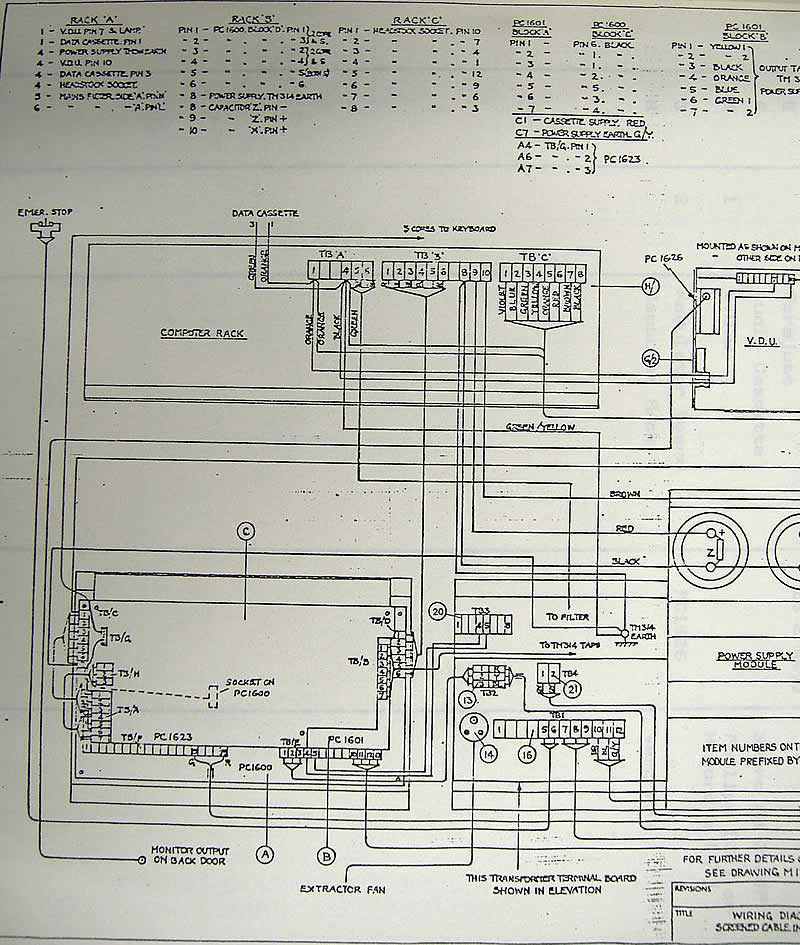
Denford Admin - That's great - it certainly clears up which terminals are in use! Thanks for digging this out.
It appears that pin4 is a common earth, and I'm guessing that pin 2 then is the 0-10V DC speed signal? Any ideas what pins 5 and 6 are - forward and reverse signals perhaphs? Does this sound sensible to you Mr Magoo?
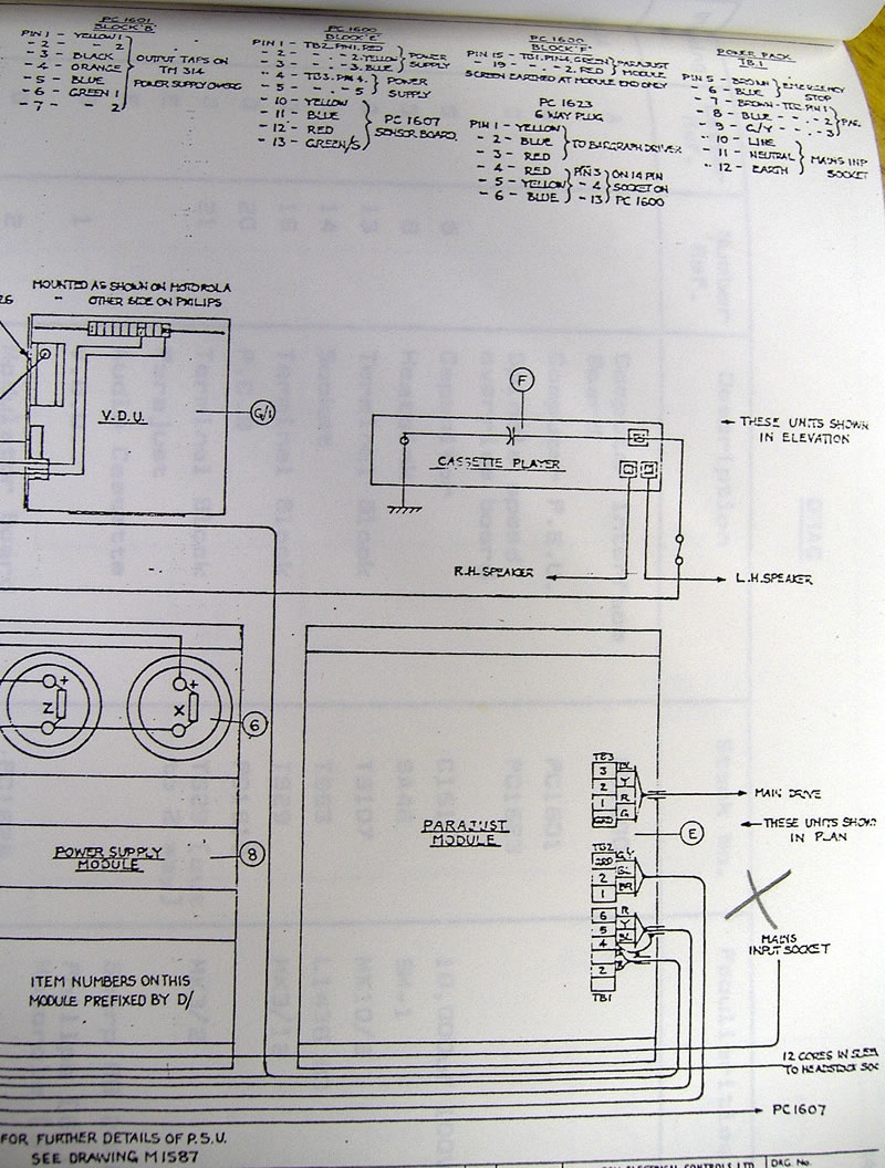
Is there any chance that Admin could perhaps post the rest of this drawing - the connections to the parajust disappear off to the bottom left of the pic, and it would be a lot of help to see where these go.
Cheers
Alastair
It appears that pin4 is a common earth, and I'm guessing that pin 2 then is the 0-10V DC speed signal? Any ideas what pins 5 and 6 are - forward and reverse signals perhaphs? Does this sound sensible to you Mr Magoo?
Is there any chance that Admin could perhaps post the rest of this drawing - the connections to the parajust disappear off to the bottom left of the pic, and it would be a lot of help to see where these go.
Cheers
Alastair
-
Denford Admin
- Site Admin
- Posts: 3635
- Joined: Fri 10 Feb , 2006 12:40 pm
- Hardware/Software: Go to User Control Panel > Profile
Enter as much information about your CNC hardware and software as you can - it makes it easier for everyone to know what you're talking about then. - Location: Sunny Brighouse
- Contact:
Ah - now it all starts to make sense...
Look at diagram L1804. 3 terminals in the bottom right hand corner (when view landscape) marked parajust show how realys on the Orac PCB are used to connect to the START and STOP connections on the parajust.
So on the PARAJUST terminal strip...
Term 4 is STOP
Term 5 is COMMON
Term 6 is START
So it looks like you should put a link between 5 and 6 to start the motor.
The only thing that is wierd on the L1804 diag is that it shows a normally closed relay contact used on the start input, and a normally open one on the stop input. I'd have expected it to be the other way round so I think the drawing could be wrong. Anyway, at the end of the day if you use a 2 pole relay to short pins (5 and 6) and also short pins (4 and 5) it looks like it should work
And with regards to the analogue, I can't see any isolation on the L1804 which means good news as the parajust must have an isolated anaogue input - the Mach3 should connect straight into it.