All info relating to the Denford Cyclone lathes
Moderators: Martin, Steve, Mr Magoo
-
Denford Admin
- Site Admin
- Posts: 3634
- Joined: Fri 10 Feb , 2006 12:40 pm
- Hardware/Software: Go to User Control Panel > Profile
Enter as much information about your CNC hardware and software as you can - it makes it easier for everyone to know what you're talking about then.
- Location: Sunny Brighouse
-
Contact:
Post
by Denford Admin » Mon 07 Sep , 2009 10:59 am
On a normal lathe the spindle usually turns towards the front/operator and viewed from the rear of the spindle this is clockwise.
Normal M codes are M3 is clockwise rotation and M4 is anticlockwise as viewed from the spindle drive end for both lathes and mills.
So yes, I would say that the Boxford was setup different to what is usual on a lathe.
I totally agree - standards are standards for a reason - M03 should
always be clockwise when looking down the spindle/headstock towards the tool/chuck
It's like making a drill which only goes in reverse, because you wired it up wrongly in the 1st place
The opinions expressed here are my own personal views and not those of the people, institutions or organizations that I may or may not be related with unless stated explicitly. I am not responsible for any action, content, products or services or for any damages or losses, directly or indirectly, caused or alleged to have been caused as a result of your use or reliance on information posted here. This forum is not intended to malign any religion, ethnic group, club, organization, association, company, or individual, or anyone or any thing, especially those with the ability and desire to fight back. I assume no responsibility for the content of any other sites or any products or services that may be offered through other sites. My intention is to do no harm, injury, defamation, or libel to others.
-
Triac whizz
- CNC Expert

- Posts: 238
- Joined: Mon 17 Jul , 2006 21:48 pm
- Location: France
Post
by Triac whizz » Mon 07 Sep , 2009 21:03 pm
Yeah I saw a b*xford video the other day it was thread cutting, the tool was in a changer at the rear but tip was uppermost....it was a while before I realised that this is daft...cos you have to spin the chuck the conventional way to drill holes!
Also the advantage of rear tool posts it that the tool springs out of the way rather than try to dig in when trying to crash
and hey Mr Admin whats that great big cop out clause in your signature?
Self Catering Lodges in Central France with covered pool & large grounds
www.la-coterie.com
-
Steve
- CNC Guru

- Posts: 1432
- Joined: Tue 21 Feb , 2006 16:15 pm
- Location: Denford UK
Post
by Steve » Tue 08 Sep , 2009 8:45 am
Having worked for both Boxford and Denford there are advantages and disadvantages to the turret orientation issue.
The spindle does run CW when drilling an CCW when turning on the Boxford turret.
The disadvantage is mainly in the threading. To cut a right hand thread the tool has to start at the chuck end and move towards the tailstock!
Internal threads will be LH.
The good thing about this orientation is that you can see the tools much better and the cutting forces are reflected downwards into the cross slide.
-
Denford Admin
- Site Admin
- Posts: 3634
- Joined: Fri 10 Feb , 2006 12:40 pm
- Hardware/Software: Go to User Control Panel > Profile
Enter as much information about your CNC hardware and software as you can - it makes it easier for everyone to know what you're talking about then.
- Location: Sunny Brighouse
-
Contact:
Post
by Denford Admin » Tue 08 Sep , 2009 8:46 am
There has always been friendly rivalry between B*xf*rd and us but I don't want anything to get out of hand - who knows who's watching!

Did you also notice what hand the thread was ? ... to cut a normal RH thread, it would have had to feed backwards (ie away from the chuck)
-
Triac whizz
- CNC Expert
- Posts: 238
- Joined: Mon 17 Jul , 2006 21:48 pm
- Location: France
Post
by Triac whizz » Tue 08 Sep , 2009 11:19 am
yup was a rh thread
Self Catering Lodges in Central France with covered pool & large grounds
www.la-coterie.com
-
black8898
- CNC Apprentice

- Posts: 58
- Joined: Tue 01 Sep , 2009 11:19 am
Post
by black8898 » Wed 09 Sep , 2009 9:00 am
Hi there
Don't know if anyone out there can give me some advice , have just fitted my new phase converter and powered up my Cyclone and everthing worke fine for around 2 hours then machine seemed to just turn itself off ,have checked all the things that I could think of but nohing , all I can say is that when I press the powere switch on Fanuc unit to turn machine on is that you hear the machine start up but then it turns off , there is power going to all cooling fans and cabinet light and they are all working . I just do not know what else to look for can anyone out there help ???
Alan
-
Denford Admin
- Site Admin
- Posts: 3634
- Joined: Fri 10 Feb , 2006 12:40 pm
- Hardware/Software: Go to User Control Panel > Profile
Enter as much information about your CNC hardware and software as you can - it makes it easier for everyone to know what you're talking about then.
- Location: Sunny Brighouse
-
Contact:
Post
by Denford Admin » Wed 09 Sep , 2009 9:19 am
That kind of behaviour normally indicates a thermal cut-out switch...ie, where things works for a bit, then shut down the power when something gets too hot. Then when it cools, it will all work again (for a while...)
-
black8898
- CNC Apprentice
- Posts: 58
- Joined: Tue 01 Sep , 2009 11:19 am
Post
by black8898 » Wed 09 Sep , 2009 9:33 am
It has had all night to cool down if it was something getting hot , with the main cabinet open when I look inside there is a small red light on and written on a label it says ESR , is that normal ?? also down in main black box when I turn machine on there is a switch / breaker that throws in then throws out almost instantly , not sure what one this is all I can say is that there is a row of switches (grey in colour) and the one that I am talking about is right next to these and is red in colour , you say thermal cut outs is it possible for me to test these ?? if so how would I go about it , do you have any other ideas ??
-
Lone_Ranger
- CNC Expert
- Posts: 220
- Joined: Mon 01 Oct , 2007 15:23 pm
-
Contact:
Post
by Lone_Ranger » Wed 09 Sep , 2009 9:34 am
.
Do you have anything on the screen at all?? If so are there any error messages??
What exactly does it do, does the screen come on and then go off or not come on at all??
Some specifics of the exact sequence of events (or lack thereof) will help!!
Did you check the output of the Inverter before connecting it and what filter system is fitted to the inverter or in the line to the Cyclone?? It may be that the output of the inverter is too "raw" and has damaged some circuitry, most inverters unless specifically made for use with electronic equipment have a pretty rough output, full of huge peaks, most are just used to drive 3 phase motors that don`t care much how rough the supply is!!!
More info needed!!
Regards
Rob
.
Regards
Rob
-
bradders
- CNC Guru
- Posts: 1251
- Joined: Mon 13 Feb , 2006 12:35 pm
- Location: Brighouse, England
-
Contact:
Post
by bradders » Wed 09 Sep , 2009 9:39 am
All the breakers should be on when the machine is running OK, If one is flipping off when you start up there is a problem. Is there any stickers / labels on the breaker, denoting what it is / does, better still post pictures of it and we may be able to tell what part of the electrics it is supplying
-
black8898
- CNC Apprentice
- Posts: 58
- Joined: Tue 01 Sep , 2009 11:19 am
Post
by black8898 » Wed 09 Sep , 2009 9:57 am
Hi Rob
the 3 phase converter is a brand new unit made by Transwave and was went through with a lot of disscusion before unit was purchased , it is a 10hp 7.5kw and the machine has worked fine for around 2 hours with no problems then the machine just seemd to turn itself off , now whta happens is that when I turn machine on from power switch on Fanuc control unit you can hear the machine turn on and then you hear it click and turn itself off then you have to press the off switch before you can try again but still have the same problem , have spoken to Transwave and they assure me 100% that the power is not to raw as you put it hope that explains what you were asking
Thanks
Alan
-
Lone_Ranger
- CNC Expert
- Posts: 220
- Joined: Mon 01 Oct , 2007 15:23 pm
-
Contact:
Post
by Lone_Ranger » Wed 09 Sep , 2009 11:32 am
.
Alan
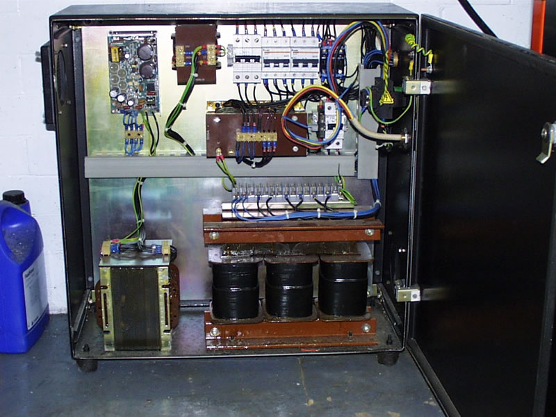
Here is a photo of the inside of my Cyclone power supply box, can you tell us which bit is/isn`t working???
One of the things to check in there, in the top left hand corner is the low volt stabilised power supply, check that for output 12V DC. This supplies the control circuits and if that`s not working then nothing works!
Also in the panel on the rear of the machine is a "Black Box" with a Big Yellow lightening flash on it, that is the main Fanuc power supply and it has some Green fuse holders down near the bottom, check those fuses.
Regards
Rob
-
Attachments
-
- cyclone power supply.jpg (105.55 KiB) Viewed 10781 times
-
black8898
- CNC Apprentice
- Posts: 58
- Joined: Tue 01 Sep , 2009 11:19 am
Post
by black8898 » Wed 09 Sep , 2009 13:02 pm
Hi Rob
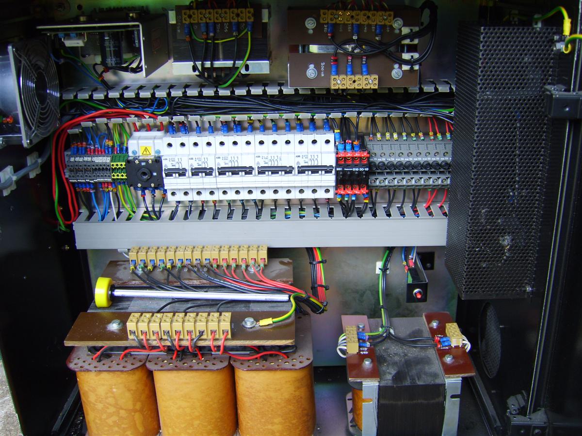
Have checked the fuses on the black box with flash on it and have found the 3.2amp fuse is not working !! so I assume that this could be the problem , where can I get a similar fuse from apart from Denford ?? the main box that you have seny me a picture of is nothing like my one I am going to try and attach a picture of my one , If you can see picture in about the middle you can see a bank of grey coloured switches and at the end of those to the right hand side there is a breaker switch coloured red that is the one that throws in when machine is turned on and then out within a couple of seconds , one last thing is there a temporary way of replacing the fuse that has gone to see if that is my problem ??
Thanks I do not know what I would do without you
Alan
-
Attachments
-
- SV200140.JPG (187.27 KiB) Viewed 10779 times
-
Steve
- CNC Guru
- Posts: 1432
- Joined: Tue 21 Feb , 2006 16:15 pm
- Location: Denford UK
Post
by Steve » Wed 09 Sep , 2009 13:54 pm
Can you identify which fuse has blown? Is it one of the grey ones to the right of the Red Contactor? What are the wire numbers that go to the fuse?
I think the Fanuc controls have a power input unit. As you connect the power the contactor pulls in and provided the voltages check out the contactor stays in.
While I have no experiance on the cyclone I have worked on the Fanuc OT controls. You will have a 24V DC supply that feeds all the guard and limit switches for inputs and outputs.
If one of these inputs shorts out (or a cable gets trapped) the 24V fuse could blow and then prevent the unit turning on,
What was the machine doing when it tripped out? Had you operated any switches, coolant pump, guard, limits etc etc prior to it shutting down?
-
black8898
- CNC Apprentice
- Posts: 58
- Joined: Tue 01 Sep , 2009 11:19 am
Post
by black8898 » Wed 09 Sep , 2009 14:00 pm
The fuse that has blown is not in the main box in the picture but in the upper cabinet , the box it comes from is the power supply box that supplies the Fanuc unit and the fuse is 3.2 amps
-
Lone_Ranger
- CNC Expert
- Posts: 220
- Joined: Mon 01 Oct , 2007 15:23 pm
-
Contact:
Post
by Lone_Ranger » Wed 09 Sep , 2009 14:04 pm
Hi Alan
The "Black Box" is the Fanuc power unit and as far as I know you will need to go to GE Fanuc for those, here is a link to the GE Fanuc online shop
http://www.gefanuc-europe.com/
Item is only €4.75 Euro plus whatever postage they stick you for!! The part number for the Fuse is A60L-0001-0046/3.2
The Black and Red unit you refer to is the MDC Contactor so if that doesn`t go in and hold in then no power distribution around the machine!!
I think you need someone from Denford to jump in here with the correct schematics for your machine as it appears to be a lot different to mine.
BTW Can you please make your photos a bit smaller, I hate all this having to scroll sideways to see stuff!! You can use MS Paint to change the size etc.
I have uploaded the schematics for my setup, the basic wiring should be very similar, all I`ve got I`m afraid!!
Regards
Rob
.
Regards
Rob
-
Attachments
-
- cyclone_b_transformer_box_161.pdf
- (42.37 KiB) Downloaded 18054 times
-
- cyclone_b_main_power_schematic_765.pdf
- (43.71 KiB) Downloaded 18066 times
-
Denford Admin
- Site Admin
- Posts: 3634
- Joined: Fri 10 Feb , 2006 12:40 pm
- Hardware/Software: Go to User Control Panel > Profile
Enter as much information about your CNC hardware and software as you can - it makes it easier for everyone to know what you're talking about then.
- Location: Sunny Brighouse
-
Contact:
Post
by Denford Admin » Wed 09 Sep , 2009 14:12 pm
BTW Can you please make your photos a bit smaller, I hate all this having to scroll sideways to see stuff!! You can use MS Paint to change the size etc.
I usually do alter the size of photos posted, but it is a bit of a pain these days with this upgraded forum (they changed the files to some kind of code, so you have no clue what file to look for - not even a file extension), so I'd appreciate smaller pics as well.
See this post about the Microsoft quick and easy image resize tool:
viewtopic.php?t=597
-
black8898
- CNC Apprentice
- Posts: 58
- Joined: Tue 01 Sep , 2009 11:19 am
Post
by black8898 » Wed 09 Sep , 2009 14:29 pm
Hi I am sorry for the size of picture entirely my fault in a rush to do things and forgot to resize it will not happen again , What I have done and again this was only to see if I had found the problem , I was asked to check the fuses in the power supply to the Fanuc unit and I did find that the 3.2 amp fuse had blown , nowI come to what I should not have done I used a strand of wire that as the thinest I could find find about one thou and repaired the fuse andreplaced in box powered up machine and yes it worked machine powered up without any problems , have now removed the fuse and am waiting for a call about replacement , manythanks to you and others who always answer these mails very quickly and have been of tremendous help to me
Thanks
Alan
-
Denford Admin
- Site Admin
- Posts: 3634
- Joined: Fri 10 Feb , 2006 12:40 pm
- Hardware/Software: Go to User Control Panel > Profile
Enter as much information about your CNC hardware and software as you can - it makes it easier for everyone to know what you're talking about then.
- Location: Sunny Brighouse
-
Contact:
Post
by Denford Admin » Wed 09 Sep , 2009 14:43 pm
FWIW I've uploaded Fanuc OTA electrical drawings:
viewtopic.php?f=15&t=2337&start=0
-
black8898
- CNC Apprentice
- Posts: 58
- Joined: Tue 01 Sep , 2009 11:19 am
Post
by black8898 » Wed 09 Sep , 2009 14:49 pm
Rob
I have already apologised on the forum about size of pic it was beacause I was rushing around and forgot to resize it will not happen again , I have found a place in Liecester that supply the fuses am just waiting for them to get back to me , what I have tried in the meantime was I took fuse apart and place a piece of wire one thou thick accross the link where fuse had blown put it back together just to try and see if that was the problem and it was machine powered up as normal have now removed the fuse and will wait until the new one arrives , thanks for you help Rob
Alan